Knowledge Center
Popular Search
esp32modespthefredo
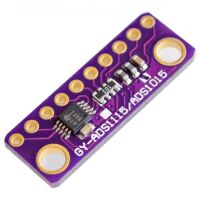
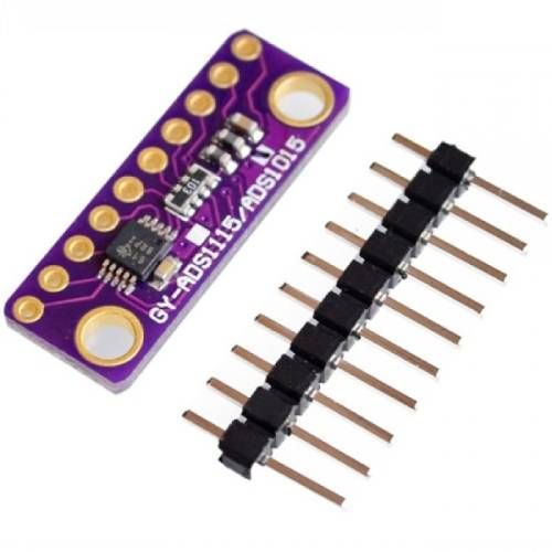
ADS1115 – Raspberry Pico
Table of Contents
Wiring #
Interfacing an ADS1115 module with a Raspberry Pi Pico is straightforward, as both devices use the I2C communication protocol. In this tutorial, we will guide you through the steps to connect and configure the ADS1115 with the Raspberry Pi Pico.
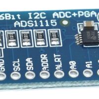
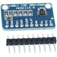
You may connect the A0, A1, A2, and A3 pins of the ADS1115 to the sensors or devices whose analog values you want to read. In this example, we will use a 10K Potentiometer.
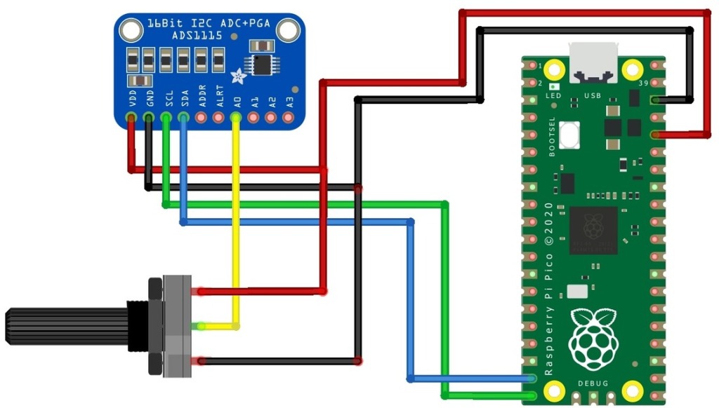
| Pico pin: | ADS1115 module pin: |
|---|---|
| +5V | +5V (VCC) |
| GND | GND |
| GP14, Pin 19 (I2C channel 1) | SDA I2C Serial Data |
| GP15, Pin 20 (I2C channel 1) | SCL I2C Serial Clock |
Script met ADS1015/ADS1115 bibliotheek #
Download Github: https://github.com/robert-hh/ads1x15
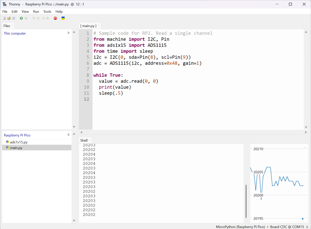
Example code
# Sample code for RP2. Read a single channel
from machine import I2C, Pin
from ads1x15 import ADS1115
from time import sleep
#i2c = I2C(0, sda=Pin(8), scl=Pin(9))
i2c = I2C(1, sda=Pin(14), scl=Pin(15))
adc = ADS1115(i2c, address=0x48, gain=1)

while True:
  value = adc.read(0, 0)
  print(value)
  sleep(.5)
Output:
Products #


Source #
https://github.com/robert-hh/ads1x15
https://how2electronics.com/ads1115-16-bit-adc-module-with-raspberry-pi-pico