


- Beschrijving
- Aanvullende informatie
- Download
- Q & A
Beschrijving
Informatie (ENG)
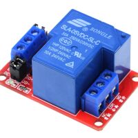
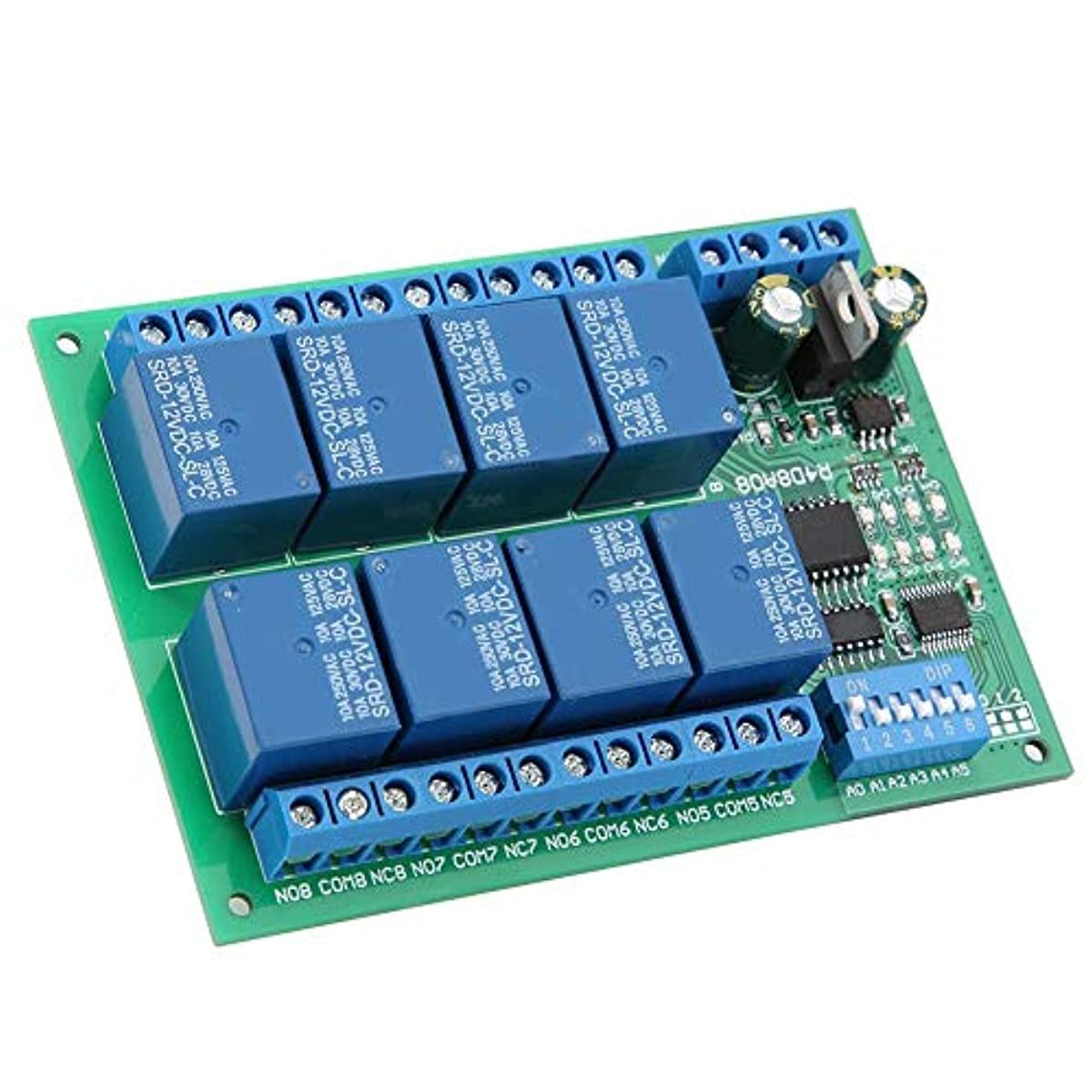
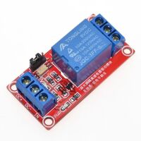
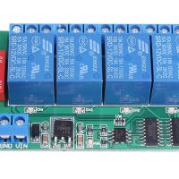
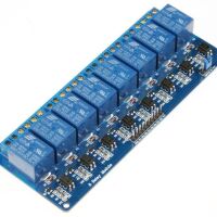
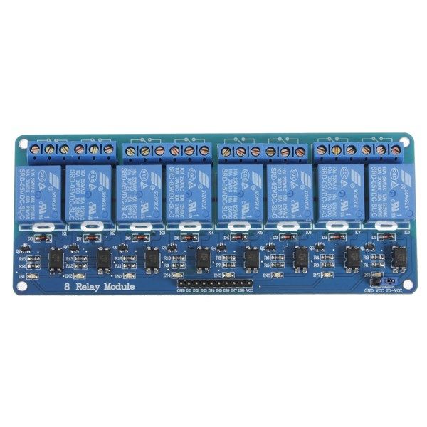
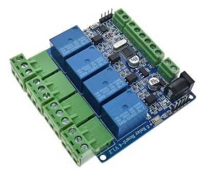
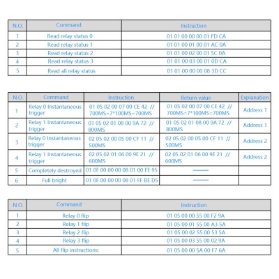
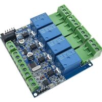
This is a 5V 4-Channel Relay interface board. Be able to control various appliances and other equipment with a large current. It can be controlled directly by a Micro-controller (Arduino, 8051, AVR, PIC, DSP, ARM, ARM, MSP430, TTL logic) . 5V 4-Channel Relay interface board and each one needs 50-60mA Driver Current. Equipped with high-current relay, AC250V 10A ; DC30V 10A.
- Working Voltage: DC 5V
- Working Current: 1A
- Work Temperature: -25℃~85℃
- Work Humidity: 5%~95%RH
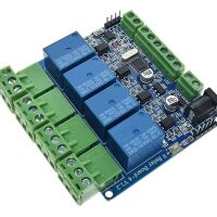
- Size: 78*78*20mm
Let op: Getoonde afbeeldingen kunnen afwijken door versie/update verschillen
Chip: STM8S003 (v1.2)
Application:
- Supports all MCU control.
- The industrial field.
- PLC control.
- Smart home control.
Features:
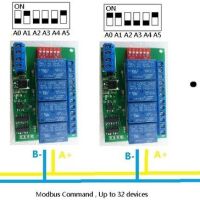
- .Modbus serial communication
- Relay switching output
- Convenient AT command control
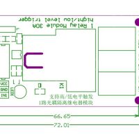
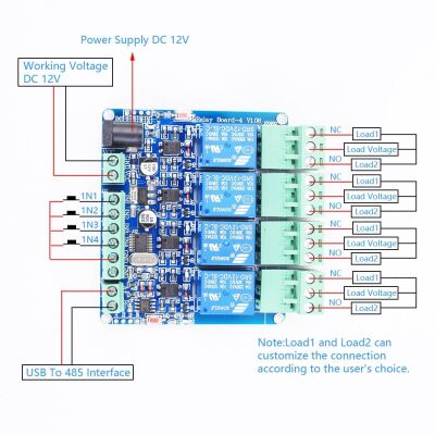
Note: IN1-IN4 cannot be connected to 230Vac (some buyers will make this mistake)
The wiring is as follows:
Pay attention to: IN1-IN4 are used to read the switch status through 485 when connected to a relay output, not through input control relay output.
IN1-IN4: The switch status needs to be checked and ready by the computer every time, and data cannot be actively sent to 485.
Pay attention to: IN1-IN4 connected to switch or voltage signal (0~5V)
IN1-GND (default is high level, low level after the switch is turned on) The computer sends instructions to read the switch status.
IN2-GND (default is high level, low level after the switch is turned on) The computer sends instructions to read the switch status.
IN3-GND (default is high level, low level after the switch is turned on) the computer sends instructions to read the switch status.
IN4-GND (default is high level, low level after the switch is turned on) The computer sends instructions to read the switch status.
Command function:
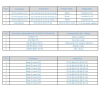
1. Set the address to
2. Read the address
3. Read the software version
4. Read the hardware version
MODBUS-RTU communication instruction:
Function code: 05 is the relay output [control relay on/off]
Function code: 06 is stored data [user-defined storage data, user-defined data, address number, set by the user. Generally useless]
/**********************************************************************/
Modbus RTU instruction
Baud rate: 9600 8 NONE 1
Send in hexadecimal
Hexadecimal reception
Steps:
1. The software sets the communication baud rate
2. Set the address (device address used for communication)
The instruction with address 1 set by default
/************************************************* ******************/
Set the address as: 01
Send: 00 06 40 00 00 01 5c 1b
Return: 01 06 00 00 00 01 48 0A
Set the address as: 02
Send: 00 06 40 00 00 02 1c 1a
Return: 02 06 00 00 00 02 08 38
Read address
00 03 40 00 00 01 90 1b
/************************************************* ******************/
Read software version
Send: 00 03 00 02 00 01 24 1b //【Sun】
Return: 01 03 02 10 00 B5 84 //No. 10
Send: 00 03 00 04 00 01 c4 1a //[month] Broadcast reading (only one device can be connected, practical for all addresses, convenient for testing)
Return: 01 03 02 4D 61 4C FC //4D[M] 61[A] MAR[March]
Send: 00 03 00 08 00 01 04 19 //【year】 Broadcast reading (only one device can be connected, practical for all addresses, convenient for testing)
Returns: 01 03 02 20 18 A1 8E //20 18 = 2018
Send: 00 03 00 10 00 01 84 1e //[Hour, Minute] //Broadcast reading (only one device can be connected, practical for all addresses, convenient for testing)
Return: 01 03 02 21 26 21 CE //21:26
Read hardware version (PCB version)
Send: 00 03 00 20 00 01 84 11 //Broadcast reading (only one device can be connected, practical for all addresses, convenient for testing)
Return: 01 03 02 00 6A 38 6B //6A = 106 =V1.06
Send: 01 03 00 20 00 01 85 c0
Return: 01 03 02 00 6A 38 6B //6A = 106 =V1.06
/************************************************* ******************/
[Address 1]
//——————————————–
Relay 0 turns on: 01 05 00 00 FF 00 8C 3A
Relay 0 is off: 01 05 00 00 00 00 CD CA
//——————————————–
Relay No. 1 turned on: 01 05 00 01 FF 00 DD FA
Relay No. 1 is closed: 01 05 00 01 00 00 9C 0A
//——————————————-
Relay No. 2 turned on: 01 05 00 02 FF 00 2D FA
Relay No. 2 is off: 01 05 00 02 00 00 6C 0A
//——————————————-
Relay No. 3 turned on: 01 05 00 03 FF 00 7C 3A
Relay No. 3 is closed: 01 05 00 03 00 00 3D CA
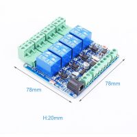
Single flip instruction:
No. 0 relay flip: 01 05 00 00 55 00 F2 9A
No. 1 relay flip: 01 05 00 01 55 00 A3 5A
No. 2 relay flip: 01 05 00 02 55 00 53 5A
No. 3 relay flip: 01 05 00 03 55 00 02 9A
Fully closed: 01 05 00 ff 00 00 fd fa
Fully open: 01 05 00 ff ff ff fc 4a
Full flip: 01 05 00 ff 5a 00 c7 5a
/************************************************* *********************/
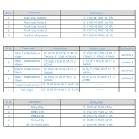
Read relay status 0: 01 01 00 00 00 01 FD CA
Read the status of relay No. 1: 01 01 00 01 00 01 AC 0A
Read the status of relay No. 2: 01 01 00 02 00 01 5C 0A
Read the status of relay No. 3: 01 01 00 03 00 01 0D CA
Relay No.1 Read all channel status: 01 01 00 FF 00 00 3d c9
/************************************************* ********************/
Read all interface input status
01 02 00 00 00 00 78 0a
return:
01 02 01 01 60 48 //IN1 press
01 02 01 02 20 49 //IN2 press
01 02 01 04 A0 4B //IN3 press
01 02 01 08 A0 4E //IN4 press
Aanvullende informatie
| Gewicht | 100 g |
|---|---|
| Afmetingen | 5 × 8 × 2 mm |