- Beschrijving
- Aanvullende informatie
- Q & A
Beschrijving
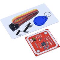
Wordt geleverd met 1×8 + 1×4 headerpins
Informatie (ENG):
PN532 NFC Module Features and Specifications:
80C51 microcontroller core with 40 Kbyte ROM and 1 Kbyte RAM
Highly integrated analog circuitry to demodulate and decode responses
Buffered output drivers to connect an antenna with minimum number of external components
Integrated RF level detector
Integrated data mode detector
RFID reader/writer mode support [MIFARE 1k, 4k, Ultra light, and DESFIRE cards, ISO/IEC 14443-4 cards such as CD97BX, CD light, DESFIRE, P5CN072 (SMX), INNOVISION Jewel cards such as IRT5001 card, FELICA cards such as RCS_860 and RCS_854]
Built in PCB Antenna, with 5cm to7cm communication distance
Supports MIFIRE higher transfer speed communication at 212Kbits/s and 424 Kbits/s
Supported host communication: SPI Interface, I2C Interface and High Speed Serial UART
Flexible interrupt using IRQ pin
Hard reset with low power function
Power down mode per embedded firmware
Automatic wake up on HSU,I2C and SPI interfaces when device is in power down mode
Programmable timer
Contactless communication at 13.56MHz
On-board level shifter, Standard 5V TTL for I2C and UART, 3.3V TTL SPI
Work as RFID reader and writer
Work as RFID card or a virtual card
Operating voltage: +2.7V to +5.5V
On-board level shifter: Standard 5V TTL for I2C and UART, 3.3V TTL SPI
Low power modes: Hard-Power-Down mode (1µA typical), Soft-Power-Down mode (22µA typical)
Operating temperature: -30ºC to +85ºC
How to use PN532 NFC module?
For using PN532 module, first we will choose the mode of communication between MODULE and CONTROLLER. As mentioned earlier this module has three interfaces, of which we have to choose one. Remember at any given point of time only one of three interfaces can be used. All three cannot be used together. We will have to choose the mode of interface using two switches solder to the board. The switches are S1 and S2 shown in pin diagram.
|
S1 |
S2 |
Interface |
|
OFF |
OFF |
HSU (High Speed UART) |
|
ON |
OFF |
I2C |
|
ON |
ON |
SPI |
Choose the mode of interface and corresponding state of switches from above table. Next toggle the switches S1 and S2 to those positions.
After choosing the type of interface, connect the module to the controller or processor. Say if you opted to use I2C, then connect module to I2C of the controller. If you opted to use SPI, then connect module to SPI of controller.
After interfacing you have to download the library files for the module from corresponding websites. Say for ARDUINO platform [https://www.arduinolibraries.info/libraries/adafruit-pn532]. Save the library files in the IDE program files.
Now all that left is to write the program for the controller or ARDUINO in the IDE software. And do call up on the saved library files while writing the program. With those libraries we can directly communicate with the module while skipping all the steps of communication protocol.
Once the programming is done, power up the circuit to get the desired response.
Applications:
Media or Data sharing
Robotics
Smart Phones and Smart devices
Security systems
Computer Peripherals
Package Identification
Theft protection systems
Aanvullende informatie
| Gewicht | 100 g |
|---|---|
| Afmetingen | 4 × 4 × 0,5 mm |