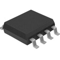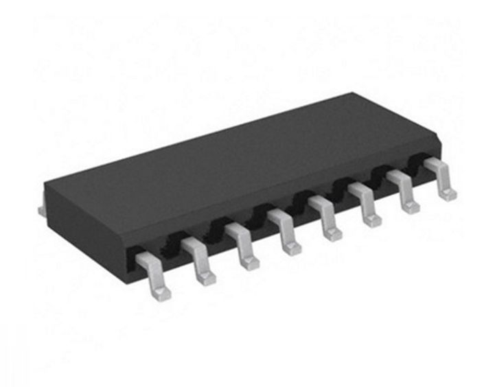
STC 15FW204S 8-Bit 8051 MCU 8-13.5MHz 4KB FLASH SOP-16
€ 1,00 incl. BTW
- Beschrijving
- Extra informatie
- Merk
- Q & A
Beschrijving
– Enhanced 8051 Central Processing Unit, 1T, single clock per machine cycle, faster 8~12 times than the rate of a traditional 8051.
– Operating voltage range: 5.5V ~ 2.4V.
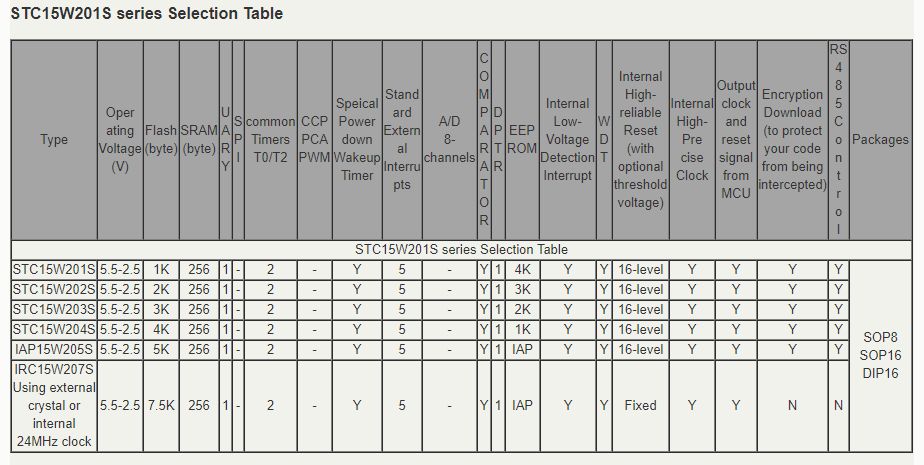
– On-chip 1K/2K/3K/4K/5K/7.5K FLASH program memory with flexible ISP/IAP capability, can be repeatedly erased more than 100 thousand times. on-chip 256 bytes SRAM
– On-chip EEPROM with large capacity can be repeatedly erased more than 100 thousand times.
– ISP/IAP, In-System-Programming and In-Application-Programming , no need for programmer and emulator.
– Internal hghly reliable Reset with 16 levels optional threshold voltage of reset, external reset curcuit can be completely removed
– Internal high- precise R/C clock(±0.3%) with ±1% temperature drift (-40℃~+85℃) while ±0.6% (-20℃ ~+65℃) in normal temperature and wide frenquency adjustable between 5MHz and 35MHz (5.5296MHz / 11.0592MHz / 22.1184MHz / 33.1776MHz).
– Operating frequency range: 0- 35MHz, is equivalent to traditional 8051:0~420MHz.
– No need external crystal and reset, and can output clock and low reset signal from MCU.
– A high-speed asynchronous serial ports—-UART ( can be regarded as 2 serial ports by shifting among 2 groups of pins): UART1(RxD/P3.0, TxD/P3.1) can be switched to (RxD_2/P3.6, TxD_2/P3.7).
– Support the function of Encryption Download (to protect your code from being intercepted).
– Support the function of RS485 Control
– Code protection for flash memory access, excellent noise immunity, very low power consumption
– Power management mode: Slow-Down mode, Idle mode(all interrupt can wake up Idle mode),
– Stop/Power- Down mode.
– Timers which can wake up stop/power-down mode: have internal low-power special wake-up Timer.
– Resource which can wake up stop/power-down mode are: INT0/P3.2, INT1/P3.3 (INT0/INT1, may be generated on both rising and falling edges), INT2/P3.6, INT3/P3.7, INT4/P3.0 ( INT2 / INT3/ INT4, only be generated on falling edge); pins T0/T2(their falling edge can wake up if T0/T2 have been enabled before power-down mode, but no interrupts can be generatetd); internal low-power special wake- up Timer.
– Two Timers/Counters—-T0(are compatible with Timer0 of traditional 8051) and T2, T0/T2 all can independently achieve external programmable clock output
– Programmable clock output function(output by dividing the frequency of the internal system clock or the input clock of external pin):
– The speed of external programmable clock output of 5V MCU is also not more than 13.5MHz, because the output speed of I/O port of STC15 series 5V MCU is not more than 13.5MHz.
– The speed of external programmable clock output of 3.3V MCU is also not more than 8MHz, because the output speed of I/O port of STC15 series 3.3V MCU is not more than 8MHz.
– The Programmable clock output of T0 is on P3.5/T0CLKO (output by dividing the frequency of the internal system clock or the input clock of external pin T0/P3.4)
– The Programmable clock output of T2 is on P3.0/T2CLKO (output by dividing the frequency of the internal system clock or the input clock of external pin T2/P3.1)
– Two timers/counters in above all can be output by dividing the frequency from 1 to 65536.
– The Programmable clock output of master clock is on P5.4/MCLKO, and its frequency can be divided into MCLK/1, MCLK/2, MCLK/4.
– The master clock can either be internal R/C clock or the external input clock or the external crystal oscillator.
– MCLK is the frequency of master clock. MCLKO is the output of master clock.
– It is on MCLKO/P3.4 that the Programmable clock output of master clock of STC15 series 8-pin MCU (such as STC15F101W series). However, it is on MCLKO/P5.4 that the Programmable clock output of master clock of other STC15 series MCU including 16-pin or more than 16-pin MCU (such as STC15F2K60S2, STC15W4K32S4 and so on)
– Comparator, which support comparing by external pin CMP+ and CMP- or internal reference voltage and generating output signal (its polarity can be configured) on CMPO pin can be used as 1 channel ADC or brownout detect function.
– One 15 bits Watch-Dog-Timer with 8-bit pre-scaler (one-time-enabled) advanced instruction set, which is fully compatible with traditional 8051 MCU, have hardware multiplication / division command.
– 14/6 common I/O ports are available, their mode is quasi_bidirectional/weak pull-up (traditional 8051 I/O ports mode) after reset, and can be set to four modes: quasi_bidirectional/weak pull-up, strong push-pull/ strong pull-up, input-only/high-impedance and open drain. the driving ability of each I/O port can be up to 20mA, but the current of the whole chip don’t exceed this maximum 90mA.
– If I/O ports are not enough, it can be extended by connecting a 74HC595. Besides, cascading several chips also can extend to dozens of I/O ports.
– In Keil C development environment, select the Intel 8052 to compiling and only contain < reg51.h >
Extra informatie
| Gewicht | 0,5 g |
|---|---|
| Afmetingen | 1 × 1 × 0,5 mm |


