- Beschrijving
- Aanvullende informatie
- Downloads
- Q & A
Beschrijving
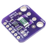
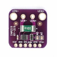
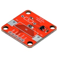
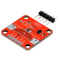
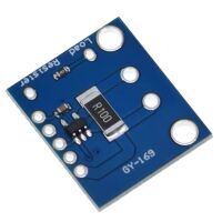
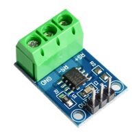
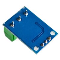
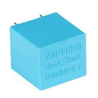
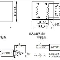
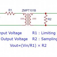
ZMPT101B is a high-precision voltage Transformer. This module makes it easy to monitor AC mains voltage up to 1000 volts. A tiny little thing the size of a bouillon cube. Holds up to 4kV per breakdown voltage, the ratio of turns is 1: 1, but this is a current transformer of 2mA: 2mA. We feed it a current and remove the current. The input current is simply set by the resistor in series R1, and we use a sampling resistor R2 in parallel to get the output voltage.
Features:
- High galvanic isolation
- Wide Range
- High accuracy
- Good Consistency
Specification:
Product model: ZMPT101B
Rated input current: 2mA
Rated output current: 2mA
Change ratio: 1000:1000
Phase difference: ≤20′
Linear range: 0~1000V 0~10mA
Linearity: ≤0.2%
Allowable error: -0.3≤f≤0.2%
Isolation withstand voltage: 4000V
Uses: accurate measurement of voltage and power
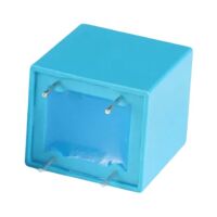
Sealing material: epoxy resin
Installation method: printed board installation
Working temperature:-40 to +60 degrees
Shell material: ABS
ZMPT 101B Transformer Calculation
R1 is chosen so that the current through the winding does not exceed 2mA, it holds a maximum of 10mA, but after 2mA linearity is lost and the output will be clear that.
Step 1: Determination of maximum output RMS voltage
VOutmax is decided by the ADC peak voltage in the sampling loop of Microcontroller.
For Bipolar ADC
VOutmax=(Peak Voltage)/(√2)
For example
As for ± 5V ADC, the maximum RMS voltage of the transformer:
VOutmax=(Peak Voltage)/(√2)=5V/(√2)=3.53V
For Unipolar ADC
VOutmax=(Peak Voltage)/(2√2)
For example
As for 0-3.3V ADC, the maximum RMS voltage of the transformer:
VOutmax=(Peak Voltage)/(2√2)=3.3V/(2√2)=1.16V
Step 2: Determination of input current-limiting resistor R1
Current-limiting resistor
R1=Vin/I
Where
Vin : Rated input voltage
I : Rated operating current ( when Coil resistance is compared with current-limiting resistor R1, it can be ignored.)
ZMPT101B usually working at rated current: 1~2mA.
When Rated input voltage ≤ 100V ,Usually choosing the operating current I=2mA; When Rated input voltage ≥ 220V,To reducing the resistor power, usually choosing the operating current 1 mA ≤ I ≤ 2 mA.
for example V=100V,I=2 mA,
R1=Vin/I=100/0.002=50kΩ
for example: V=220V,I=1.1 mA,
R1=Vin/I=220/0.0011=200kΩ
To improve reliability, the current-limiting resistor selected usually is greater than its 4 times the rated power, and generally, uses a high temperature coefficient metal film resistor.
Step 3: Determination of the sampling resistor R2
R2=VOutmax/I=(VOutmax/Vin)×R1 Ω
for example: Voutmax =3.53V,Vin =100V
R2=VOutmax/I=(VOutmax/Vin)×R1=(3.53/100)×50 kΩ=1.765kΩ
The above formula is also suitable for the two ways of active and passive output.
When selecting the sampling resistor, Resistor should not exceed
R2=VOutmax/I=VOutmax/Vin×R1 Ω
Aanvullende informatie
| Gewicht | 15 g |
|---|---|
| Afmetingen | 3 × 3 × 2 mm |